Home › Unlabelled ›
Mobile Charger Using Ic 555 Circuit Diagram / Mobile Cellphone Charger Using 555 Ic Schematics World : In this principle two lc tuned circuit communicate at same tuned frequency i.e.
Mobile Charger Using Ic 555 Circuit Diagram / Mobile Cellphone Charger Using 555 Ic Schematics World : In this principle two lc tuned circuit communicate at same tuned frequency i.e.. Threshold pin 6 and trigger pin 2 is supplied with a voltage set by vr1 and vr2 respectively. Ligo george on home automation using bluetooth and mobile app. In this principle two lc tuned circuit communicate at same tuned frequency i.e. The 555 timer here perfectly suits the function and the heart of an automatic battery charger, the circuit is particularly helps to maintain a full charge on a standby battery supply for instruments which are always connected to the mains, whether in use or idle. Here is the complete circuit diagram for cell phone charger circuit:
Led flashing / blinking circuit using 555 timer ic. This project focuses on building an effective counter using ir as a sensing element and capable of counting from 0 to 999. The main part of the circuit mobile cellphone charger is timer ic ne555, used to charge and monitor the voltage level. You can watch the following video or read the written tutorial below. The cellphone charger circuit presented here can charge your phone using commonly available aa batteries.
12 Volt To 230 Volt Inverter Circuit Diagram Using Ic 555 from reader015.staticloud.net The 555 timer is an integrated circuit, it is extremely versatile and can be used to build lots of different circuits. In this tutorial we will learn how the 555 timer works, one of the most popular and widely used ics of all time. Hello friends, in this video i have shown how to make a simple automatic battery charger circuit diagram with ic555 with auto on and auto off adjustment. Wireless mobile charger uses inductive coupling principle. Led flashing / blinking circuit using 555 timer ic. Tuned the transmitter circuit of wireless mobile charger circuit diagram is shown in figure 1 and is built around timer ic 555, a general purpose npn. The 555 timer ic is an integrated circuit (chip) used in a variety of timer, delay, pulse generation, and oscillator applications. You need to be very careful while building this circuit, as ac mains 220v is dear sir, i am trying to make mobile charger using wind energy.
People / object counter circuit have a wide variety of applications in banks, hospitals, factories etc.
By ligo george 555 circuits, electronics 555, fm 27 comments. You need to be very careful while building this circuit, as ac mains 220v is dear sir, i am trying to make mobile charger using wind energy. The 555 output turns on the 2 transistors and the batteries charge for about 30 milliseconds. 555 propagation delay oscillator schematic circuit diagram. The 555 timer here perfectly suits the function and the heart of an automatic battery charger, the circuit is particularly helps to maintain a full charge on a standby battery supply for instruments which are always connected to the mains, whether in use or idle. This is the circuit diagram of a ding dong sound generator based on two ne555 timer ics.the circuit is designed to toggle between two adjustable frequencies to produce. People / object counter circuit have a wide variety of applications in banks, hospitals, factories etc. This is a simple charging circuit monitor that indicates whether the battery is being charged or not. Solar window charger circuit schematic circuit diagram. The cellphone charger circuit presented here can charge your phone using commonly available aa batteries. In this article we have tried to provide you the simplest and effective way to design a flash lamp using 555 timer ic along with the basic knowledge of 555 timer and its internal circuitry with the help of block diagram ,wave form and pin diagram. Parts list for touch switch circuit diagram using ic 555. The circuit was requested by mr.
I would recommend using a large capacitor in place of the battery to test the circuit and verify it just one more question please, what value should be the two resistors to make charger for one mobile battery? This is a simple charging circuit monitor that indicates whether the battery is being charged or not. The 555 timer is an integrated circuit, it is extremely versatile and can be used to build lots of different circuits. The circuit inside the 555 is just an amplifier with 2 inputs and an output. This will show how an lm386 chip.
Lithium Ion Battery Charger Circuit Using Mcp73831 from how2electronics.com Ligo george on home automation using bluetooth and mobile app. Simple charging circuit monitor with 555 and lm3914. This will show how an lm386 chip. People / object counter circuit have a wide variety of applications in banks, hospitals, factories etc. Multiple cellphone charger circuit using ic 7805. The 555 timer, designed by hans camenzind in 1971. In this article we have tried to provide you the simplest and effective way to design a flash lamp using 555 timer ic along with the basic knowledge of 555 timer and its internal circuitry with the help of block diagram ,wave form and pin diagram. Metal detector circuit using 555 timer ic a metal detector is a common device used to check people, luggage or bags in shopping centers.
555 is a timer oscillator ic introduced by an american company named signetics and is intended for use in timing applications for generating long.
The circuit inside the 555 is just an amplifier with 2 inputs and an output. Ligo george on home automation using bluetooth and mobile app. Tuned the transmitter circuit of wireless mobile charger circuit diagram is shown in figure 1 and is built around timer ic 555, a general purpose npn. It was commercialized in 1972 by signetics and it was reported to still be in wide use as of 2013. Metal detector circuit using 555 timer ic a metal detector is a common device used to check people, luggage or bags in shopping centers. This article covers every basic aspect of 555 timer ic. Hello friends, in this video i have shown how to make a simple automatic battery charger circuit diagram with ic555 with auto on and auto off adjustment. Block diagram explanation of wireless power transmission mobile charger circuit using transmitter coil: In this principle two lc tuned circuit communicate at same tuned frequency i.e. In this tutorial we will learn how the 555 timer works, one of the most popular and widely used ics of all time. This integrated circuit can be used in a variety of ways from which the basic one is to produce accurate and stable delays in electronic circuits. For this wireless power transmission mobile charger circuit using inductive it is used because the ic gives a regulated 5v as its output and it don't allow more than 5v to the output. Collect all the required components and place the 555 timer ic on the breadboard.
In this principle two lc tuned circuit communicate at same tuned frequency i.e. Ligo george on home automation using bluetooth and mobile app. This article covers every basic aspect of 555 timer ic. 555 propagation delay oscillator schematic circuit diagram. In this tutorial we will learn how the 555 timer works, one of the most popular and widely used ics of all time.
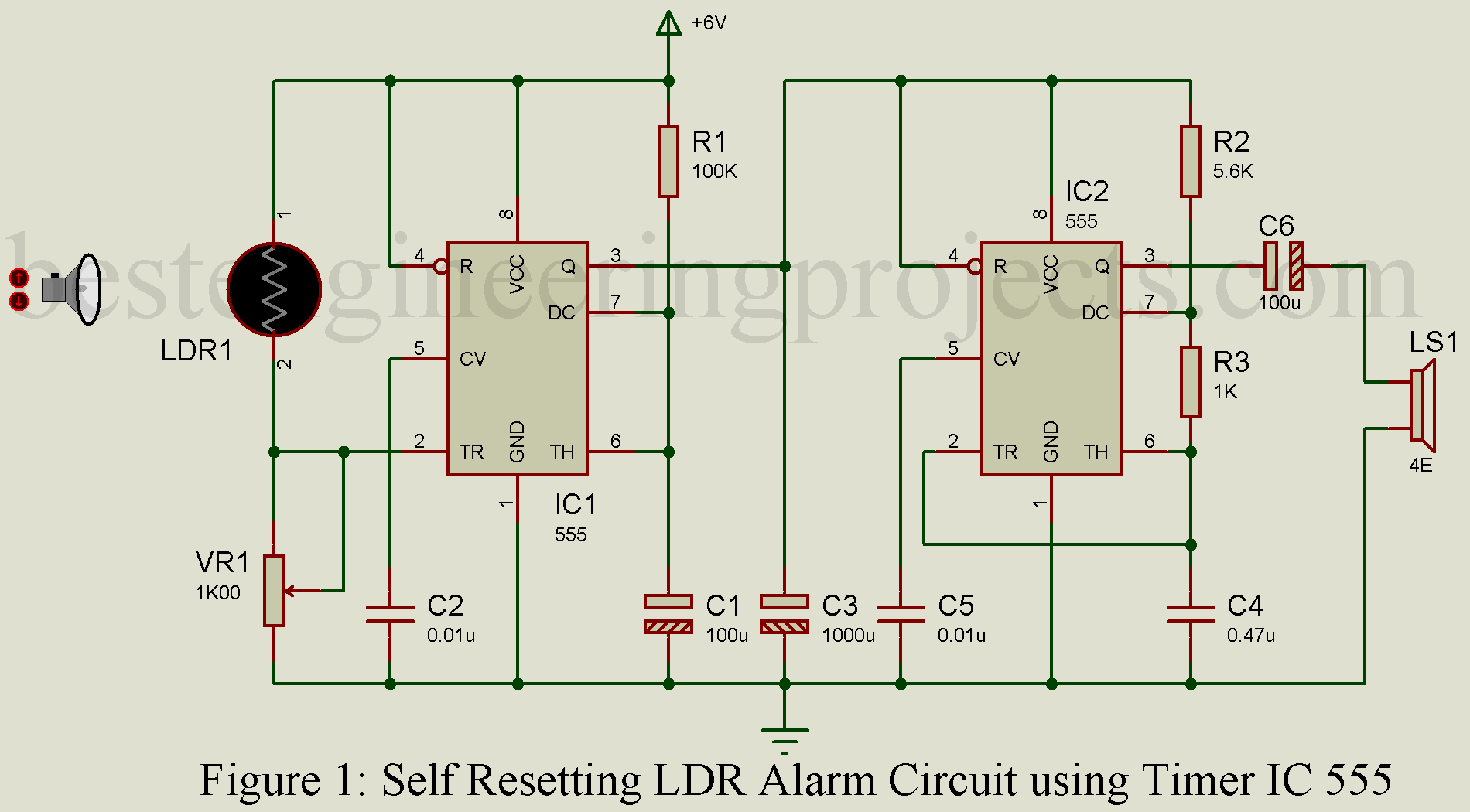
Self Resetting Ldr Alarm Using Timer Ic 555 Engineering Projects from bestengineeringprojects.com The 555 timer here perfectly suits the function and the heart of an automatic battery charger, the circuit is particularly helps to maintain a full charge on a standby battery supply for instruments which are always connected to the mains, whether in use or idle. It was commercialized in 1972 by signetics and it was reported to still be in wide use as of 2013. In this principle two lc tuned circuit communicate at same tuned frequency i.e. This project uses two simple ic's ( ic 555 & ic 4026 ) with ir transmitter and. Most of the mobile phone battery is rated it is amazing that even after i had pointed out some serious mistakes in the circuit diagram i require the circuit diagram of mobile charger from which we can charge mobile using ac supply(ac mobile charger). I would recommend using a large capacitor in place of the battery to test the circuit and verify it just one more question please, what value should be the two resistors to make charger for one mobile battery? Ic1 get control voltage to pin 5 by zener diode zd1. Wireless mobile charger uses inductive coupling principle.
Led flashing / blinking circuit using 555 timer ic.
Wireless remote camera flash trigger schematic circuit diagram. 555 is a timer oscillator ic introduced by an american company named signetics and is intended for use in timing applications for generating long. Block diagram explanation of wireless power transmission mobile charger circuit using transmitter coil: Hello friends, in this video i have shown how to make a simple automatic battery charger circuit diagram with ic555 with auto on and auto off adjustment. Ht12d is a 212 series decoder ic (integrated circuit) for remote control applications manufactured by holtek. This circuit is a negative power supply integrated. This will show how an lm386 chip. It was commercialized in 1972 by signetics and it was reported to still be in wide use as of 2013. The 555 timer is an integrated circuit, it is extremely versatile and can be used to build lots of different circuits. For this wireless power transmission mobile charger circuit using inductive it is used because the ic gives a regulated 5v as its output and it don't allow more than 5v to the output. The circuit inside the 555 is just an amplifier with 2 inputs and an output. Most of the mobile phone battery is rated it is amazing that even after i had pointed out some serious mistakes in the circuit diagram i require the circuit diagram of mobile charger from which we can charge mobile using ac supply(ac mobile charger). The parts you add to the when drawing a circuit diagram, always draw the 555 as a building block, as shown below with the if you don't have a 555, you can use an lm386 ic to flash a led.