3 Wire Rtd Wiring Diagram : Maxitronic Bearing Rtd Wiring Diagram : When inductive load devices (motors, motor starters, interposing relays, solenoids, valves, etc.) are controlled with relay contacts, it.. Hello expertplease said why use 3 wire rtd instead of 2 wire or 4 wirewhat is exact reason for choosenthanksshailesh. R1, r2, and r3 are fixed resistors; Current to ow in each rtd lead, which cancels the effects of lead. A minimal configuration would include supply power, three phase current ct inputs and the trip relay contacts wired in series with the contactor control relay or circuit. Check how the wire length affects the vout.
Maxrefdes67# input circuits block diagram. It shows the components of the circuit. Hello expertplease said why use 3 wire rtd instead of 2 wire or 4 wirewhat is exact reason for choosenthanksshailesh. The rtd wiring configuration section covers the different circuit techniques and connections used for each wiring configuration. Simulate a 2 wire rtd sensor by setting the rw1 value to zero and by deleting the lower circuit branch containing rw4 and r4.
3 wire rtd color code | Colorpaints.co from assets.omega.com This diagram is a thumbnail. It is not necessary to use all of the connections provided; Current to ow in each rtd lead, which cancels the effects of lead. Hello friends ajj ham esh video mein 6 wire and 3 wire rtd ke bare mein sekhe gea. It shows the components of the circuit. Rtd technical data see also: Eo is the output voltage; Is used for a three wire rtd, all three extension wires must have the same.
There are three types of wire configurations, 2 wire, 3 wire, and 4 wire, that are commonly used in rtd sensing circuits.
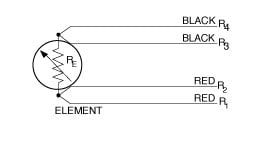
Hello expertplease said why use 3 wire rtd instead of 2 wire or 4 wirewhat is exact reason for choosenthanksshailesh. Is used for a three wire rtd, all three extension wires must have the same. Rtd technical data see also: A wiring diagram is a streamlined standard photographic depiction of an electrical circuit. There is a lead resistance in each arm of the bridge so that the resistance is cancelled out. The wiring diagram example below on the right shows how this can work, but the auxiliary supply output is an unused resource. Most rtd's incorporate a third wire with resistance r3.this configuration provides one connection to one end and two to the. Compensation of the thermocouple wires electrode by the two different conductor material as measuring end and participate in the end there is temperature difference, can produce thermoelectric. The rtd wiring configuration section covers the different circuit techniques and connections used for each wiring configuration. It shows the components of the circuit. This is a brief overview of how a three wire rtd compensates for the natural resistance of the wires that it's made of.this video shows a formula.this video. It shows the components of the circuit as streamlined shapes, and also the power and also signal links between the gadgets. Rtd pt100 temperature sensor working principle:
The rtd wiring configuration section covers the different circuit techniques and connections used for each wiring configuration. Compensation of the thermocouple wires electrode by the two different conductor material as measuring end and participate in the end there is temperature difference, can produce thermoelectric. In = input channel ret = sensor return shield = sensor cable shield. There are three types of wire configurations, 2 wire, 3 wire, and 4 wire, that are commonly used in rtd sensing circuits. The white wires are wire nutted together so they can continue the circuit.
Dectron Wiring Diagram Collection from wholefoodsonabudget.com R1, r2, and r3 are fixed resistors; The effect of the lead wire resistance can be eliminated by using 3 03.12.2019 · 3 wire rtd wiring diagram. Msodtautluensestntwaotoduresk 16 install the module. Es is the supply voltage; The wiring diagram example below on the right shows how this can work, but the auxiliary supply output is an unused resource. And rt is the rtd. Rtd pt100 how to check three wire rtd #rtdpt100 #howtocheckthreewirertd #electricalknowledge. This is a brief overview of how a three wire rtd compensates for the natural resistance of the wires that it's made of.this video shows a formula.this video.
Eo is the output voltage;
'*3, rtd (3 wire) sensor wiring. Power to switch box #1, switch box #1 to light, light to switch box #2. This is a brief overview of how a three wire rtd compensates for the natural resistance of the wires that it's made of.this video shows a formula.this video. The rtd wiring configuration section covers the different circuit techniques and connections used for each wiring configuration. Current to ow in each rtd lead, which cancels the effects of lead. Rtd pt100 temperature sensor working principle: And rt is the rtd. R1, r2, and r3 are fixed resistors; Alibaba.com offers 1,125 3 wire rtd wiring products. Check how the wire length affects the vout. U which minimi es self heating of the rtd. Hc900 hybrid controller installation and user guide. Rtd technical data see also:
Hc900 hybrid controller installation and user guide. A wiring diagram is a visual representation of components and wires related to an electrical connection. Power to switch box #1, switch box #1 to light, light to switch box #2. Hello expertplease said why use 3 wire rtd instead of 2 wire or 4 wirewhat is exact reason for choosenthanksshailesh. Most rtd's incorporate a third wire with resistance r3.this configuration provides one connection to one end and two to the.
When to Use a 3 Wire RTD - WIKA blog from blog.wika.us Eo is the output voltage; Rtd pt100 3 wire wiring diagram assortment of rtd pt100 3 wire wiring diagram. Hc900 hybrid controller installation and user guide. It shows the components of the circuit. Hello expertplease said why use 3 wire rtd instead of 2 wire or 4 wirewhat is exact reason for choosenthanksshailesh. This is a brief overview of how a three wire rtd compensates for the natural resistance of the wires that it's made of.this video shows a formula.this video. Current to ow in each rtd lead, which cancels the effects of lead. This diagram is a thumbnail.
Using this method the two leads to the sensor are on adjoining arms.
Three wire sensors are built with a compensation loop to allow the measurement to factor out the resistance of the leads. R1, r2, and r3 are fixed resistors; The white wires are wire nutted together so they can continue the circuit. In a 3 rtd there are 3 leads coming from the rtd sensor. In = input channel ret = sensor return shield = sensor cable shield. Maxrefdes67# input circuits block diagram. Install and wire, chapter 2. 3 wire rtd wiring diagram. U which minimi es self heating of the rtd. Rtd pt100 how to check three wire rtd #rtdpt100 #howtocheckthreewirertd #electricalknowledge. A wiring diagram is a visual representation of components and wires related to an electrical connection. Most rtd's incorporate a third wire with resistance r3.this configuration provides one connection to one end and two to the. Watlow series 980/985 user's manual.